This text is a result of my discussion on propellers with Mr Spencer Greenhalgh from whom a have learnt a lot.
Note: This text contains mathematical formulas and derivations. However, these could be easily skipped without considerable loss of the information value.
1. Fluid dynamics
Each text book on aerodynamics contains a lot of information on flow theory, boundary layer, Reynolds number, etc. It is, however, almost impossible to find any answer on very basic questions as „Why does it fly?“, „How the propeller generates its thrust?“, etc. So, we will have to start with basics which is:
1.1 Newton’s second law F=m*a
For fluids this law can be reordered as F = M*Δv. Accordingly, an aerodynamic force is a product of fluid flowrate (in kilograms per second) and od velocity change (in meters per second).
Please imagine a cross section through a wing moving in the air.

The lift of the wing is a result of the red arrow, or of the difference between the vectors upstream and downstream the wing.
In the other words, if there is to be an aerodynamic force there must be a change in the stream direction.
Still in other words, an airplane can fly because the wing deflects the air stream downwards.
1.2 First law of aerodynamics
The air was still before the airplane passed, now the air is moving as the red arrow indicates. The still air had no energy, now it has some. It means the air obtained some energy and the airplane, accordingly, lost some energy.
This is very different from what we know from the “normal” world – a chair can stay on a floor for years without lossing any of its energy. A flying object (whether it is an airplane, a bird, an insect) must supply energy to the air if it wishes to fly.
I call it the first law of aerodynamics, although you cannot find anything like that in the text books.
1.3 Efficiency
How much energy is lost? A kinetic energy is proportional to M*Δv*Δv (or square (Δv)). Thus, the force is proportional to M*Δv and the lost energy to M*Δv^2. It is obvious that small Δv leads to the less losses, while the force magnitude can be supported by larger flowrate M.
Please note that there could be two types of aerodynamic forces – desirable, say a lift, and undesirable, say a drag. However, both produce losses.
1.4 Examples
Wing aspect ratio: it is generally recognised that an airplanes with slimmer wings (with higher aspect ratio) fly “better”. The larger the wingspan the more air is affected (M is increased) therefore Δv could be smaller and the efficiency is better.
Propeller: if a propeller is to generate a thrust there must be stronger wind dowstream than upstream.

2. Propeller efficiency
As has been explained above the aerodynamic forces can be classified as desirable and undesirable. When talking about the propelles, the desirable force is the propulsion force which generates the thrust. The undesirable forces are just braking forces which consume energy without doing anything particularly useful.
2.1 Froude’s momentum theory
This is very simple approach to derive the propulsion efficiency. While the exact derivation is quite complicated, it can perhaps be deducted rather intuitively.
As indicated by the Fig. 2 above, the stream velocity before the prop is V, while the velocity after the prop is V+ΔV. The velocity exactly at the propeller is then V+ΔV/2 (actually, this is it which is hard to derive but quity easy to see).
Now, the propeller provides the thrust at the velocity V (the prop moves at that speed) but works (transfer its energy to air) at V+ΔV/2. Then the propulsion efficiency can be deducted to be eta_p=V/(V+ΔV/2).
This simple theorem also can be used for deducting a well known formula for the propeller absorbed power = K*N^3*D^5
Here it is:
power = force * velocity
force = mass flowrate * velocity change
mass flowrate = density * propeller disc area * velocity
When assuming a stationary prop then velocity change is proportional to
velocity. Neglecting all constants:
power = disc area * velocity^3
Disc area = D^2
Velocity = pitch * rotational speed
Accordingly, power = D^2 (P N)^3
If P/D = const then power = D^5 N^3 (and thrust = D^4 N^2)
2.2 Blade element theory

Now a bit of maths. The Fig. 3 shows the forces and velocities on the propeller blade. The prop od diameter D is rotated with a rotational speed of N, and advances forward with a velocity V. The propeller airfoil creates a lift force Fy and a drag force Fx. Both these aerodynamical forces can be composed into a thrust T and a braking force B.
D – propeller diameter
S – propeller pitch
N – rotational speed
alfa – propeller (theoretical) pitch angle
beta – propeller actual pitch angle
k – ratio between Fy and Fx (Lift/Drag)
x – ratio V/(piDN)
Then:
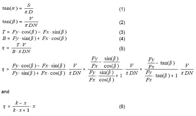
In fact, the formulas above makes it possible to calculate the propeller properties if the blade geometry and airfoil properties are known. When doing so it is necessary to „correct“ the velocities, both in axial and tangential directions. The actual velocity at the blade is, as explained above, V’=V+ΔV/2, and similar correction applies, to a much lesser extend, also for the rotational speed.
Also, the equation (6) gives the maximum achievable efficiency (or a general efficiency curve) for a given k (=L/D of the airfoil) and non-corrected x. I have been using k=17, maybe even 20 could be OK.
Another interesting fact is that if k increases this eta increases as well, and can eventually reach 1 for any x. In other words, if there is no airfoil drag this efficiency (non-corrected for inflow) is always 1.
3.3 Total propeller efficiency
Then perhaps the total efficiency can be calculated as a product of the propulsion efficiency (which pertains to the desired force – a thrust) and of mechanical efficiency (expressing the unwanted losses – say a friction in this 2D model) calculated from the inflow corrected Eq. (6).
Assuming that:
1. Lift coefficient is proportional to the angle of attack, drag coefficient is constant
2. Stream velocity downstream the prop is constant (pitch x RPM)
Neither assumption holds true, but both are reasonable simplifications.
Then following curves can be calculated:

Efficiency curves for a single propeller – propulsion efficiency, mechanical efficiency and total efficiency. It is illustrated that mechanical efficiency decreases with the speed of flight, while the propulsion efficiency increases. Accordingly there must be a peak on the efficiency curve. Again, please be aware that the aim of this paper is an explanation, not to provide the exact values.
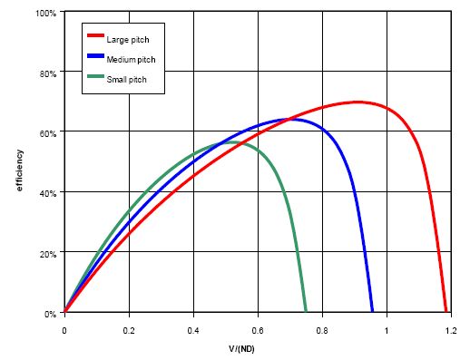
How the pitch does influence the efficiency. The peak efficiency is larger with the large pitch as the propeller can make less revolutions per same advancement. Less revolutions means less energy lost due to the drag. On the other hand, at small advancement velocities the propulsion efficiencies are smaller as the downstream is faster.
This approach wanted to be descriptive rather than accurate.
Now, what has Spencer taught me.
1. My studies have been based on the NACA Technical note (TN) 14, while Spencer uses TN333. The propeller efficiencies calculated by his method seem to be closer to the reality than there gives „my“ TN14 method.
2. There exists a program called propcalc (downloadable from the same site as Drivecalc). This program makes it possible to enter the geometry of the prop, blade airfoil polars, and calculates the propeller performance curves. The Propcals results are reasonably close to the findings of the TN333 document.
3. A rate of climb of an electric powered sailplane can be evaluated from a formula RoC = P/(10M)*D/(D+15) (explanation on RC Groups)
RoC – rate of climb in m/s
P – input power in watts
M – model weight in kilograms
D – propeller diameter in inches
Nice and simple, I like it.
Jan
27.11.2010
1 komentář
Komentáře nejsou povoleny.